Angular tolerance
A pedal lever has a short arm of 40 mm and a long one of 600 mm, with an angle of 120° between them. The drawing carries a general tolerance, and by the shorter leg ISO 2768 gives ±30′. A protractor on the bend accepts the lever. But 30′ over 600 mm is 5.2 mm at the end of the arm, while the pin hole has to land within half a millimetre. The same requirement can be stated in two ways, and for a long side the statement in millimetres is the honest one.
An angular tolerance limits how far an angle may deviate from nominal. It is given in angular units, ±Δα, or in linear ones — as a distance t over a length L. There is one link between them: t = L · tg Δα. A minute over 100 mm is 0.029 mm, over a metre — 0.29 mm. The longer the side, the more millimetres the same minute gives, so general angle tolerances get tighter as the length grows.
| Notation | ±Δα — on an angular dimension · ∠ t A — angularity tolerance in a frame, t in mm |
| Link between the statements | t = L · tg Δα; for small angles t ≈ L · Δα, Δα in radians |
| Reference figures | 1′ = 0.029 mm per 100 mm · 1″ = 4.85 µrad = 4.85 µm per metre |
| General tolerances | ISO 2768-1, class m, by the shorter leg: up to 10 — ±1°, 10–50 — ±30′, 50–120 — ±20′, 120–400 — ±10′, over 400 — ±5′ |
| Tolerance grades | GOST 8908: AT1…AT17; ATα in µrad and angular units, ATh = ATα · L₁ · 10⁻³ in µm |
| Where | chamfers and bevels, machine-tool slideways, V-blocks and squares, bends, welded assemblies, frame layout |
01 · Definition
Minutes at the vertex, millimetres at the end
An angle without a length cannot be judged on the spot: on a short bevel 30′ give a tenth of a millimetre, on a metre-long flange — almost nine. That is why an angular tolerance has two statements. Minutes are convenient when the sides are short and the angle is checked with a protractor. Millimetres are convenient when the point at the end of a long side matters: a part is mounted there, a hole is drilled, a bracket is welded on.
The statement in millimetres is the angularity tolerance of ISO 1101. The surface must lie between two parallel planes a distance t apart, inclined to the datum at the nominal angle. The zone is not tied to the vertex; it only limits the rotation of the face. A straight face of length L rotated by δ takes up a width of L · tg δ. Hence t = L · tg Δα, and both statements specify the same thing, but only for the length at which they were compared.
Minutes go down, millimetres go up
The rows are length ranges of the shorter leg. On the left — the angle tolerance in minutes; the bar and the figure on the right — the same minutes in millimetres at the upper limit of the range, logarithmic scale. The line is 0.1 mm.
Five parts, two statements, one angle
The main action is the «Start check» button. The part is placed on a surface plate, and the vernier protractor reads the angle to 2′. Then the part is set on a sine bar so that the checked face lies horizontal. The dial indicator travels along the face, and its reading over the length L is the same angle deviation, only in millimetres. As the last step the face is checked against the tolerance zone: by the general tolerance in minutes or by the requirement in millimetres. Below the scene you choose the part — a dead centre, a dovetail slide, a V-block, an engineer’s square or a pedal lever — the general tolerance class and the statement by which the part is accepted. The «Next part» button takes the next one from the batch.
—
02 · Conversion
Quick reckoning: 1′ ≈ 0.3 mm per metre, 1″ ≈ 5 µm per metre, 1° ≈ 17.5 mm per metre. Hence ±10′ over 250 mm is 0.73 mm, ±30′ over 600 mm — 5.2 mm.
Not to be confused with slope: a slope of 1:100 is 34′, the ratio of rise to length. A tolerance of ±34′ is the spread of the angle, not the angle itself.
| ±Δα | mm per 100 | mm per 1 m | where it occurs |
| {k} | {v} | {h} | {n} |
03 · Orders of magnitude
04 · Measuring instruments
05 · Writing rules
Series · Drafting and CAD
desk tips for every sheet06 · Neighbouring units
07 · Historical section
An angle is measured in two ways. A protractor compares it with a circular scale and gives minutes. A sine bar and indicator reduce the angle to two lengths — the gauge block height and the indicator travel — and give micrometres over a length. The second way is more precise: gauge blocks and the indicator hold micrometres, and over 100 mm of travel a micrometre is 2″.
A short face limits the accuracy of any method. On an 8 mm bevel an indicator with a 1 µm division resolves 26″, a protractor only 2′. That is why ISO 2768 gives a short side ±1°: it cannot be checked more precisely without optics. The longer the side, the more precisely it can be measured and the tighter the general tolerance.
Catalogue of quantities
the whole index →The seven SI base units
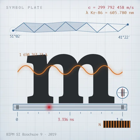
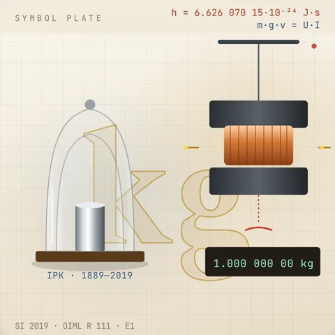
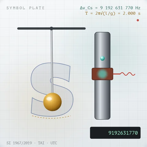
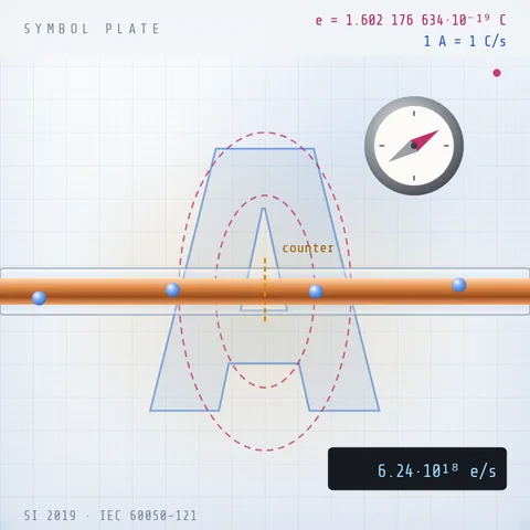
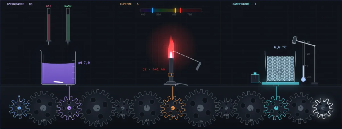
A drop of acid changes the colour of the juice, salt colours the flame, water freezes at a tap. Below them are all Simetrium sheets, by discipline and alphabetically.
Open the index →