STL tessellation tolerance
A housing for a 608 bearing was drawn in AutoCAD with a Ø22 hole and sent to print. The bearing does not fit. Calipers read 21.67 across flats and 22.00 across corners. In the model the hole was a circle, but in the STL it became an 18-gon: export with the default settings split it into facets of 20°. Each chord deviates by 0.17 mm, which is 0.33 on the diameter.
The STL format stores no arcs: any surface in it is a set of triangles. The accuracy of this substitution is set by two tolerances. The chord tolerance h limits how far a facet may move away from the surface, in millimetres. The angle tolerance α limits the turn between adjacent facets. The number of facets on a circle is the larger of the two requirements. Each triangle takes 50 bytes in a binary file, so accuracy is paid for in size.
| Notation | h — chordal deviation, mm; α — angle between facets, ° |
| Link | h = R(1 − cos π/n) ≈ π²R / 2n²; n = π / arccos(1 − h/R) |
| Number of facets | n = max(n by chord, 360°/α); twice the facets — 4 times smaller h |
| Diameter across flats | D · cos(π/n): a Ø22 hole of 18 facets — 21.67 |
| File size | binary STL: 84 + 50 · T bytes, T — number of triangles |
| Where | export for 3D printing, slicers, CNC from a mesh, scanning and comparison with CAD |
01 · Definition
Arc, chord and the deviation between them
A circle of radius R is divided into n chords. Each chord departs inward from the arc, most of all at its middle. That distance is the chordal deviation: h = R(1 − cos π/n). For large n it is almost equal to π²R / 2n². Double the number of facets — the deviation drops fourfold. Double the radius at the same n — the deviation doubles.
That is why one tolerance is not enough. A chord tolerance in millimetres is equally accurate on a gear and on a tank, but on a 0.5 mm radius it gives three or four facets. The angle tolerance keeps the shape of small fillets, but on a large radius it leaves facets visible to the eye. The export takes both and for each arc chooses the larger number of facets of the two. Facet vertices lie on the surface, while the facets cut inside convex surfaces and bulge into holes: a hole in an STL is always smaller, a shaft is always thinner.
How many facets a circle gets
The rows are radii from a fillet to a tank. The bar is the number of facets by the chord tolerance, logarithmic scale. On the right — triangles for a cylinder of that radius.
Five parts, two tolerances, two printers
The main action is the «Start export» button. In CAD the part is smooth: blue isolines lie on the true surfaces. On export it is covered with triangles, and the counter counts them and the file size. The magnifier shows one chord and its deviation. Then the file goes to the printer: the part grows layer by layer, and facets remain on it if they are coarser than the printer’s XY step. The last step is the check on the part’s main dimension. Below the scene you choose the part — a bearing bushing, a ball knob, a roller, a lamp shade or an O-ring — the export tolerance and the printer. The «Smooth surface» button overlays the true shape on top of the facets.
—
02 · Conversion
Quick estimate: n ≈ π · √(R / 2h). For R 10 and h 0.01 — about 70 facets, for R 100 — about 220. For printing, a sensible chord tolerance is two to four times finer than the printer’s XY step.
STL stores no units. A slicer reads the number 22 in the file as 22 mm, and a program working in inches — as 22 inch. The chord tolerance is set in drawing units, so in a drawing in metres «0.01» is a centimetre.
| facets n | angle | h at R 10 | Ø20 across flats | where it occurs |
| {k} | {v} | {h} | {a} | {n} |
03 · Orders of magnitude
04 · Measuring instruments
05 · Writing rules
Series · Drafting and CAD
desk tips for every sheet06 · Neighbouring units
07 · Historical section
The chordal deviation is the same sagitta that masons and carpenters used to lay out arches: from the chord and the sagitta they recovered the radius. The formula h = R(1 − cos π/n) is geometry, not a standard. STL standards set no tolerances: they are chosen by whoever exports, to suit the printer and the purpose of the part.
The approximation error adds to the printing error. If the chordal deviation is 0.17 mm and the printer holds 0.1, the hole comes out 0.3–0.5 mm smaller. If the deviation is 0.001 mm, it drowns in the printing error, while the file grows hundreds of times. The sensible point is when a facet is just finer than what the machine can show.
Catalogue of quantities
the whole index →The seven SI base units
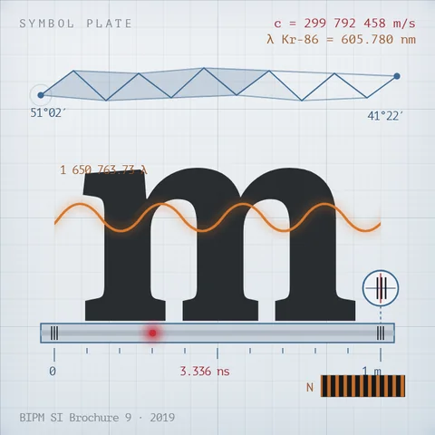
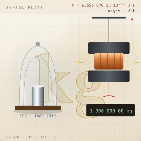
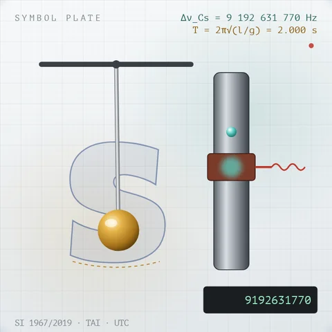
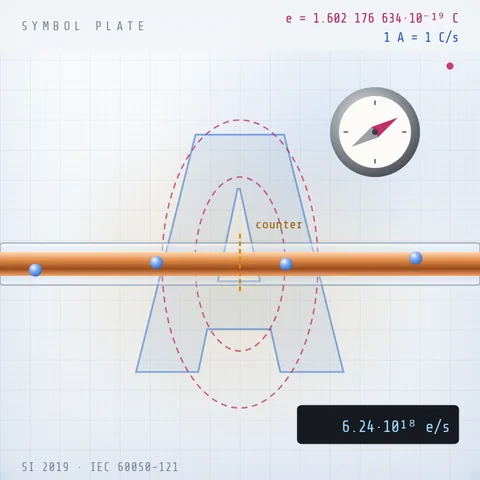
A drop of acid changes the colour of the juice, salt colours the flame, water freezes at a tap. Below them are all Simetrium sheets, by discipline and alphabetically.
Open the index →