H7/g6 fit
A bronze cam follower roller sits on a steel pin Ø16 H7/g6. The bore of the roller is 16.000 to 16.018 mm, the pin 15.983 to 15.994. The clearance is 6 to 35 µm, and the roller spins at a flick of the finger. In winter, at −40 °C, bronze shrinks more than steel and eats up 6 µm of clearance. A pair made of the tightest bore and the thickest pin seizes solid.
A fit is the character of the joint between a hole and a shaft of the same nominal size. Each part is given a letter and a digit. The letter is the fundamental deviation, i.e. the position of the tolerance zone relative to the zero line; the digit is the tolerance grade, the width of the zone. H is a hole with a lower deviation of 0, the basis of the hole-basis system; g is a shaft slightly below nominal. The two zones give the maximum and minimum clearance or interference.
| Notation | Ø16 H7/g6 — a fraction: the hole zone above, the shaft zone below |
| Hole H7 | ES = +18, EI = 0 µm — for sizes over 10 up to 18 mm |
| Shaft g6 | es = −6, ei = −17 µm |
| Clearances | Smax = ES − ei = 35 µm · Smin = EI − es = 6 µm · fit tolerance 29 µm |
| Character | clearance fit, a «sliding fit»: rollers and gears on pins, spool valves, spindle quills |
| Neighbours in the series | H8/f7 — close running · H7/h6 — locational · H7/k6 — transition · H7/n6 — tight · H7/s6 — press |
01 · Definition
Two zones and the zero line
The zero line is the nominal size, 16.000. The tolerance zones are laid off above and below it. The H hole zone always starts at zero and goes up by the tolerance IT7. The g shaft zone lies below zero: upper deviation −6 µm, zone width IT6. The hole is always larger than the shaft, and there is always clearance between them.
If the shaft zone is raised above the hole zone, you get an interference fit: the shaft is thicker than the hole and is pressed in. If the zones overlap, it is a transition fit: one pair will have clearance, another interference. In the hole-basis system only the shaft changes, while the hole is made with one reamer and checked with one gauge.
From clearance to interference
The rows are hole-basis fits. The bar runs from the maximum interference (left end) to the maximum clearance (right end), µm. The line is zero. Green — clearance fits, yellow — transition, violet — interference. Choose the diameter.
Five assemblies, six fits, three temperatures
The main action is the «Start assembly» button. One pair of parts is taken from the batch: the dial bore gauge measures the hole, the micrometer the shaft. Both sizes are plotted on the tolerance zone diagram below the scene, and you see at once what clearance or interference you get. Then the pair is assembled: a clearance fit by hand, an interference fit on the press, and the press shows the force. Then the assembly goes into the climate chamber at its working temperature. Bronze and aluminium expand more than steel and cast iron, and the clearance changes. Below the scene you choose the assembly — a roller on its pin, a die-set pillar, a piston rod in a gland bush, a drill bushing or a valve seat — the fit and the temperature. The «Next pair» button takes the next pair from the same batch.
—
02 · Conversion
The tolerance grows with diameter roughly as a cube root: IT7 on Ø16 is 18 µm, on Ø40 — 25, on Ø100 — 35. The H7/g6 fit on Ø100 gives a clearance of 12 to 69 µm.
Thermal correction: Δ = d · (α of hole − α of shaft) · (t − 20). Bronze on steel Ø16 — 0.1 µm per degree, aluminium on cast iron Ø36 — 0.45 µm per degree.
| fit | hole | shaft | S / N, µm | where |
| {k} | {v} | {h} | {s} | {n} |
03 · Orders of magnitude
04 · Measuring instruments
05 · Writing rules
Series · Drafting and CAD
desk tips for every sheet06 · Neighbouring units
07 · Historical section
All ISO 286 tolerances apply at 20 °C — the standard reference temperature for measurement under ISO 1. A steel shaft Ø16 warmed by the palm by 10 degrees grows by 1.8 µm — a tenth of the IT7 zone. That is why parts are soaked in the laboratory before measurement, and gauges are held by heat-insulating grips.
The limit clearances are the worst case: the tightest hole with the thickest shaft. In a batch such pairs hardly ever occur. Sizes follow the normal law, and the probable clearance lies near the middle, about 20 µm for Ø16 H7/g6. This is the basis for the statistical calculation of dimensional chains and for selective assembly, where parts are sorted into size groups.
Catalogue of quantities
the whole index →The seven SI base units
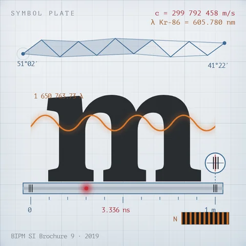
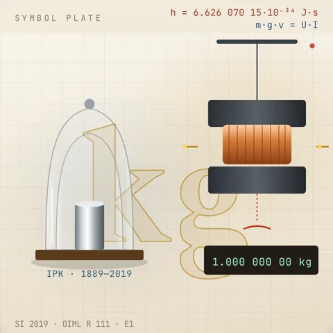
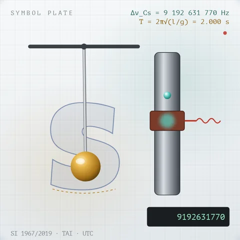
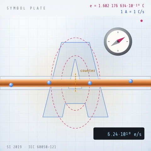
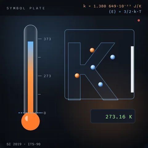
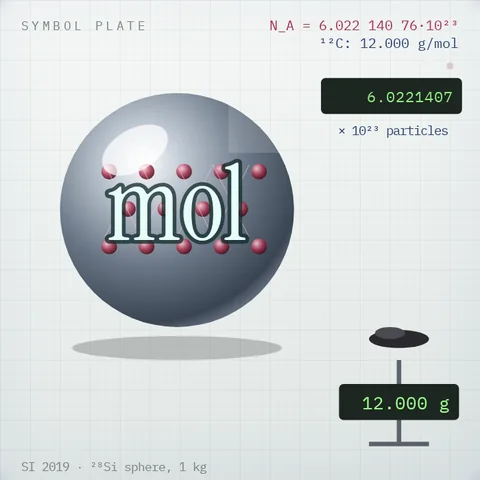
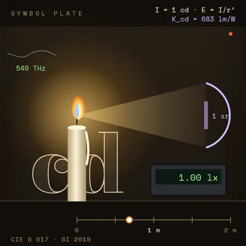
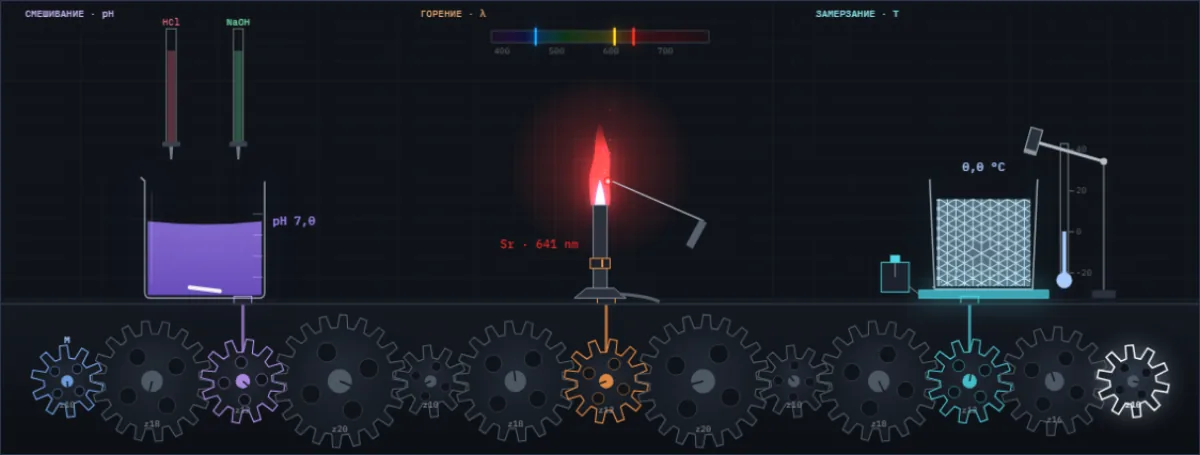
A drop of acid changes the colour of the juice, salt colours the flame, water freezes at a tap. Below them are all Simetrium sheets, by discipline and alphabetically.
Open the index →