Second moment of area
A 50×200 board lies on a span of four metres, with 3 kN at midspan. Laid on edge, it deflects by 12 mm and holds with a margin. The same board is laid flat, and under the same load it breaks. The section area has not changed, the wood is the same. What has changed is the second moment of area: 3333 cm⁴ on edge and 208 cm⁴ flat — 16 times less.
The second moment of area about an axis is the sum of the elementary areas of the section multiplied by the square of their distance to the axis: I = ∫y² dA. Material far from the axis works harder, which is why sections are made with flanges: the metal is taken to where it gives more. The section modulus W = I / ymax — the same second moment of area divided by the distance to the most stressed fibre. The first sets the stiffness of the beam, the second its strength.
| Notation | Ix, Iy — about axes through the centroid; Wx, Wy |
| Units | I — length to the fourth power: cm⁴, mm⁴, m⁴; W — to the third: cm³, mm³ |
| Rectangle | I = b·h³/12, W = b·h²/6; h — the side across the axis, in the direction of the load |
| Axis shift | parallel axis theorem: I = I₀ + A·a², a — distance between the axes |
| Where it is used | σ = M / W — strength check; f = F·L³ / (48·E·I) — deflection of a beam with a force at midspan |
| Where to find it | rolled section tables — GOST tables; for any outline — MASSPROP in AutoCAD |
01 · Definition
Area times the square of the lever arm
In bending, the beam rotates its sections: the fibres on one side are stretched, on the other compressed, and the neutral axis in the middle keeps its length. The elongation of a fibre is proportional to its distance y from the axis, so is the stress, and the moment of that stress adds one more y. That is why y² enters the sum, and a section resists bending the more strongly the farther from the axis its material lies.
Hence the cube of the height for a rectangle: doubling the height means increasing I eight times, and W four times. Hence also the flanges of rolled sections and hollow tubes: a flange moved a distance a away from the axis adds A·a² by the parallel axis theorem. The load does not «notice» the section width b nearly as much: it enters to the first power.
Same metal — different I
All sections in the rows have the same area — the same amount of metal per metre of beam. The bar is the second moment of area about the horizontal axis, logarithmic scale. On the right — I and W. Choose the area.
Five sections, two positions, one force
The main action is the «Start test» button. The beam is laid on two supports, and a press ram with a load cell comes down onto its middle from above. The force rises to the set value, the deflection gauge under the middle shows the deflection, and the strain gauge on the bottom fibre shows the stress. The deflection is compared with the calculation f = F·L³/(48·E·I), the stress with the design strength of the material. If σ = M / W exceeds it, the beam loses its strength: steel yields and stays bent, wood breaks. Below the scene you choose the section — a board, a channel, a rail, a steel flat bar or an aluminium extrusion — the position «on edge» or «flat», and the load. The slider rewinds the test.
—
02 · Conversion
The power decides: 1 cm⁴ = 10 000 mm⁴, while 1 cm³ = 1000 mm³. CAD in millimetres gives I in mm⁴ — it is divided by 10⁴ to compare with the section tables.
American section tables give I in in⁴: 1 in⁴ = 41.62 cm⁴, 1 in³ = 16.39 cm³. A W8×10 beam has 30.8 in⁴, that is 1282 cm⁴.
| cross-section | Ix, cm⁴ | Wx, cm³ | A, cm² | note |
| {k} | {v} | {h} | {a} | {n} |
03 · Orders of magnitude
04 · Measuring instruments
05 · Writing rules
Series · Drafting and CAD
desk tips for every sheet06 · Neighbouring units
07 · Historical section
The second moment of area is not measured with an instrument: it is calculated from dimensions. So the accuracy of I is set by the accuracy of the height. For a 100×10 flat bar laid flat, a thickness error of 0.2 mm is 2 % of the thickness and 6 % of the second moment of area. Rolled sections have plus and minus tolerances, and section tables give I for the nominal dimensions.
The check is done by testing. The beam is loaded in steps, E·I is calculated from the deflection and compared with the design value. A discrepancy of more than 5–10 % is a reason to look for the cause: knots and cracks in wood, incomplete penetration in a welded section, compliance of the supports. Strain gauges on the fibres check W the same way.
Catalogue of quantities
the whole index →The seven SI base units
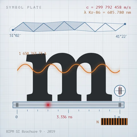
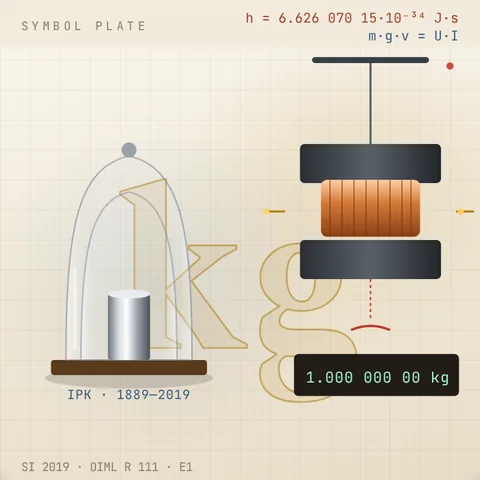
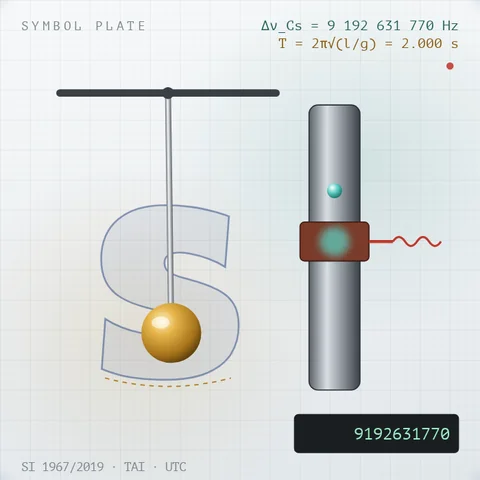
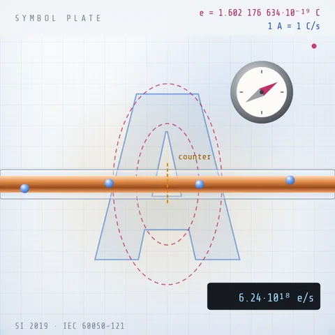
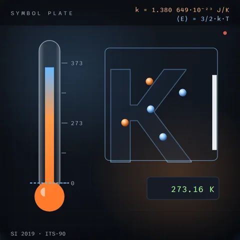
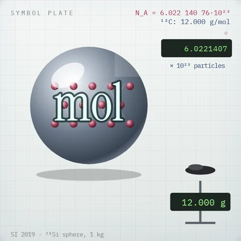
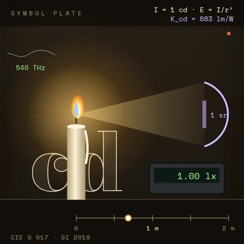
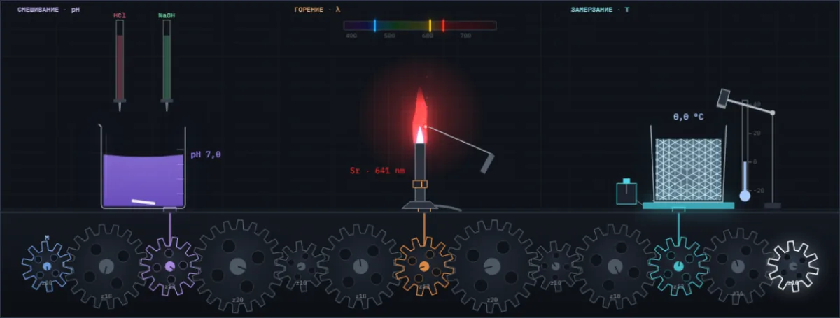
A drop of acid changes the colour of the juice, salt colours the flame, water freezes at a tap. Below them are all Simetrium sheets, by discipline and alphabetically.
Open the index →