Weld leg
Two T-joints have been welded with one and the same 5 mm leg: one by manual arc, the other by submerged-arc automatic. The gauge shows 5 on both. Under load the first one shears along the narrowest section of the weld — the height of the inscribed triangle, 3.5 mm. The second carries one and a half times more: the automatic machine penetrates the root deeper, and 1.1k goes into the calculation instead of 0.7k.
The leg of a fillet weld is a side of the largest isosceles right triangle inscribed in the weld section. It is visible from outside, it is specified on the drawing and checked with a gauge. The weld breaks along the height of that triangle, dropped from the root onto the hypotenuse. That is why shear is calculated on the section a × L, where a = βf · k, and βf depends on how deep the arc has penetrated the root.
| Notation | k — leg, mm, on the drawing ⊿k · a — design throat of the weld |
| Definition | a side of the isosceles right triangle inscribed in the section of a fillet weld |
| Shear check | τ = F / (βf · k · Lw) ≤ Rwf · γc; for E42 electrodes Rwf = 180 MPa |
| Coefficient βf | manual arc 0.7 · semi-automatic 0.8 · submerged-arc automatic 1.1 (SP 16.13330, Table 39) |
| Limits | kf,min — by the thickness of the thicker part; kf,max = 1.2 t of the thinner one, at the toe of an angle — 0.9 t |
| Typical values | 3 mm — thin sheet; 5–8 — T-joints and gussets; 8 — the single-pass limit for manual arc; 10–20 — multi-pass welds |
01 · Definition
A side of the triangle, but the height does the work
A fillet weld fills the corner between two parts. The largest isosceles right triangle is inscribed in its section; its side is the leg k. The reinforcement of a convex weld is not part of the leg, while in a concave weld the inscribed triangle is smaller than the width of the weld at its edges — its leg is smaller than it looks.
A weld loaded along or across fails along the smallest section — the height of the triangle from the root to the hypotenuse: 0.707k. The codes take a = βf · k. With manual arc the root is penetrated shallowly, βf = 0.7. Semi-automatic welding gives 0.8, submerged-arc automatic penetrates the root by several millimetres, and βf = 1.1 — the design throat is greater than the leg itself.
5 kN per centimetre of weld
The rows are the legs of the series. The bar is the shear stress τ in a weld carrying 5 kN on every centimetre of length. The line is Rwf = 180 MPa. Blue welds hold, red ones shear along the section a.
Five joints, three processes, one leg
The main action is the «Start welding» button. The torch runs along the weld: arc, sparks, a red-hot pool, cooling down to temper colours. Then the weld is cut and etched — the section shows the leg, the root penetration and the design throat a. The gauge checks the leg, and the tensile testing machine pulls the part until the weld shears along the section a or withstands the design load. Below the scene you choose the joint — a T-joint, a lap joint, an angle on a gusset plate, a pipe to a flange or a bracket stiffener — the specified leg, the welding process and the weld profile. The slider rewinds the test.
—
02 · Conversion
Quick reckoning for manual arc: a centimetre of weld with leg k carries about 1.26k kN at Rwf = 180 MPa. ⊿5 — 6.3 kN/cm, ⊿8 — 10 kN/cm.
The design weld length is taken 1 cm shorter than the actual one: the weld ends are not fully fused. A weld shorter than 4k or 40 mm is not counted at all.
| k | a = 0.7k | q, kN/cm | where |
| {k} | {v} | {h} | {n} |
03 · Orders of magnitude
04 · Measuring instruments
05 · Writing rules
Series · Drafting and CAD
desk tips for every sheet06 · Neighbouring units
07 · Historical section
The leg is measured from outside to about half a millimetre: a gauge with a 1 mm scale division, a set of plates in one-millimetre steps. For ⊿3 that is 15 % of the size, for ⊿10 — 5 %. That is why small legs are specified with a margin, and the leg tolerance under GOST 5264 is plus 1–2 mm, with no minus allowed.
The design throat cannot be measured from outside at all: it depends on the root penetration, which is visible only on a section. The codes build it into the coefficient βf for the welding process, and on the product it is the leg and the weld shape that are checked. A concave weld 5 mm across at the edges may have a leg of 4.3 — and it is rejected by the gauge.
Catalogue of quantities
the whole index →The seven SI base units
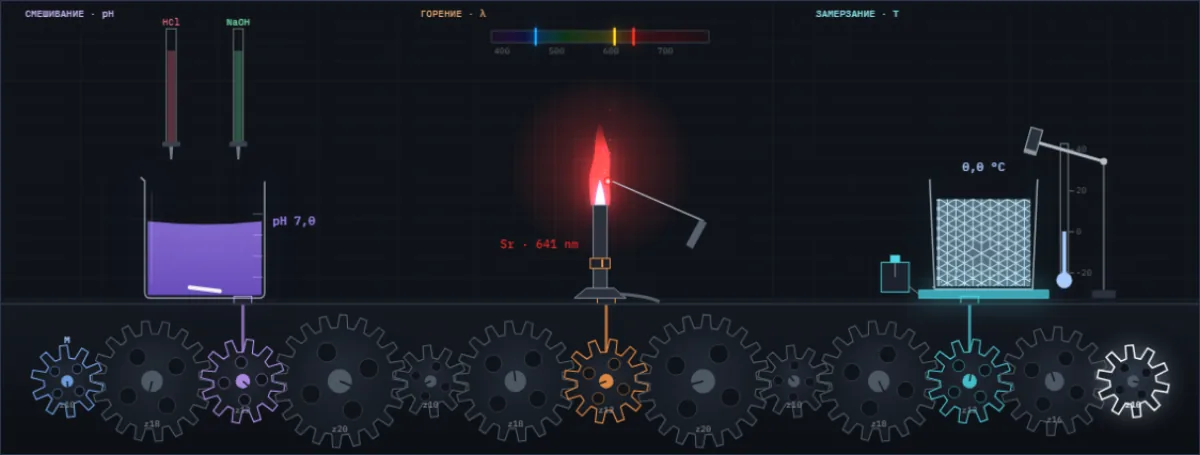
A drop of acid changes the colour of the juice, salt colours the flame, water freezes at a tap. Below them are all Simetrium sheets, by discipline and alphabetically.
Open the index →